
chapter 2
ESP32 Microcontroller
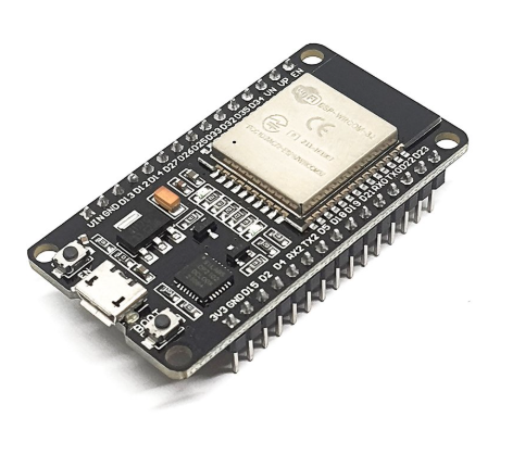
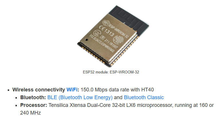
ESP32 is a family of low-cost, energy-efficient microcontrollers that integrate both Wi-Fi and Bluetooth capabilities. These chips feature a variety of processing options, including the Tensilica Xtensa LX6 microprocessor available in both dual-core and single-core variants, the Xtensa LX7 dual-core processor, or a single-core RISC-V microprocessor. In addition, the ESP32 incorporates components essential for wireless data communication such as built-in antenna switches, an RF balun, power amplifiers, low-noise receivers, filters, and power-management modules. Typically, the ESP32 is embedded on device-specific printed circuit boards or offered as part of development kits that include a variety of GPIO pins and connectors, with configurations varying by model and manufacturer. The ESP32 was designed by Espressif Systems and is manufactured by TSMC using their 40 nm process. It is a successor to the ESP8266 microcontroller.
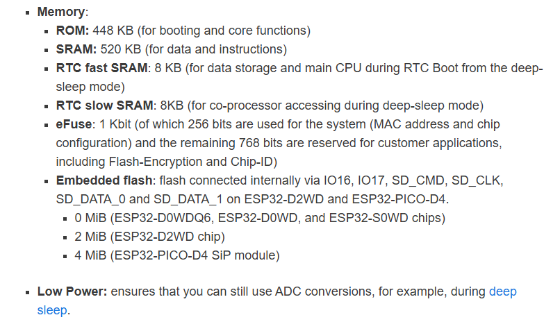
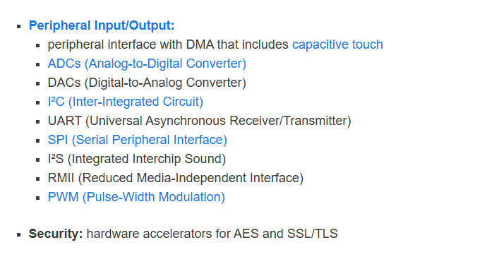
The ESP32 peripherals include:
-18 Analog-to-Digital Converter (ADC) channels
-3 SPI interfaces
-3 UART interfaces
-2 I2C interfaces
-16 PWM output channels
-2 Digital-to-Analog Converters (DAC)
-2 I2S interfaces
-10 Capacitive sensing GPIOs
The ADC (analog to digital converter) and DAC (digital to analog converter) features are assigned to specific static pins. However, you can decide which pins are UART, I2C, SPI, PWM, etc – you just need to assign them in the code. This is possible due to the ESP32 chip’s multiplexing feature.
Although you can define the pins properties on the software, there are pins assigned by default as shown in the following figure (this is an example for the ESP32 DEVKIT V1 DOIT board with 36 pins
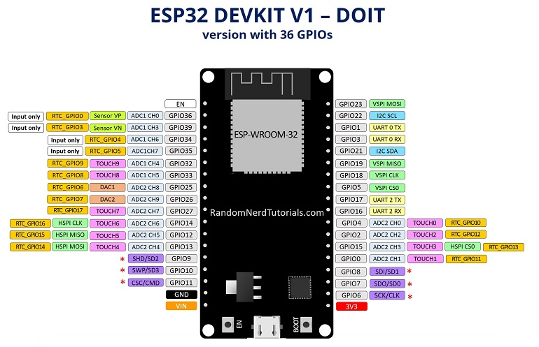
https://randomnerdtutorials.com/getting-started-with-esp32/#esp32-intro
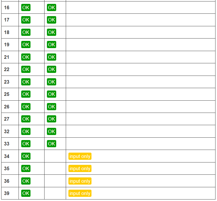
Additionally, there are pins with specific features that make them suitable or not for a particular project. The following table shows what pins are best to use as inputs, outputs and which ones you need to be cautious.
The pins highlighted in green are OK to use. The ones highlighted in yellow are OK to use, but you need to pay attention because they may have an unexpected behavior mainly at boot. The pins highlighted in red are not recommended to use as inputs or outputs.
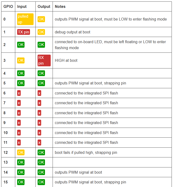
https://randomnerdtutorials.com/esp32-pinout-reference-gpios/