chapter 5
Serial communication
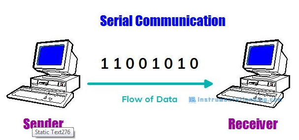
Serial communication is a fundamental aspect of microcontroller programming, and it plays a crucial role in enabling devices to exchange information. In the world of Arduino, serial communication is a powerful tool that allows you to send and receive data between your Arduino board and other devices, such as computers, sensors, displays, and more. In this article, How Does Serial Communication Works in Arduino, I will be covering everything from the basics to advanced techniques.
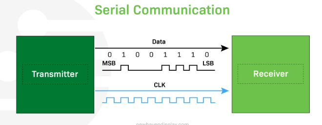
serial communication, data is sent sequentially, usually as a stream of binary digits (0s and 1s). This method allows for reliable and efficient data transmission over long distances and between different devices. Serial communication can be either synchronous (data is sent at a constant rate, synchronized by a clock signal) or asynchronous (data is sent without a clock signal and relies on agreed-upon timing parameters).
Serial communication is a commonly used method with which to exchange data between computers and peripheral devices. Serial transmission between the sender and receiver are subject to strict protocols which provide security and reliability and have led to its longevity. Many devices from personal computers to mobile devices make use of serial communication. Let’s take a closer look at its fundamentals.
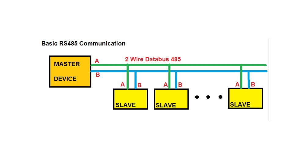
Serial communication makes use of a serial digital binary method of exchanging data. It employs a number of interfaces and serial communication protocols including RS232,RS485, SPI, and I2C among others.
How are Serial Communication work
we must first understand the fundamental concept of a bit, the smallest unit of data in an electronic circuit. A bit, in its simplest terms, is like a single piece of digital information. You can think of it like a light switch that can only be in one of two positions: 'on' or 'off'. In the language of computers, instead of 'on' or 'off', we say that a bit can be either '1' or '0'.
In serial communication, data transmission occurs bit by bit on a single communication line or channel. This process means that data bits are sent one after the other in a sequence or series (hence the term 'serial'), with the receiving device collecting and reassembling these bits into a complete message.
In simple terms, serial data transmission is like a single-lane road where cars can only travel one after the other, not side by side. Here is a simple breakdown of how serial data is transmitted:
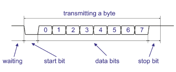
1. Start of communication: The device sending the data, called the transmitter, sends a start bit to the device receiving the data, known as the receiver. The start bit is like a heads-up, signaling, "Hey, I'm about to send some data."
2. Data transmission: Next, the transmitter sends the data bit by bit in a specific order. It's like sending a long message, one letter at a time.
3. End of communication: When all the data bits have been sent, the transmitter sends a stop bit, saying, "That's it, I've sent everything I had to send."
4. Error checking (optional): The receiver then checks if it has received the data correctly. This is done through a process known as parity checking. If the data isn't correct, the receiver can ask the transmitter to resend the data.
The telegraph was one of the first devices for long-distance serial communication, using a single wire to transmit data. Serial communication protocols and standards began to develop in the 1960s. These protocols, such as RS-232, SPI, I²C, RS485, USB, and MIPI, are widely used in electronic circuits, LCDs, OLEDs, computer systems, embedded systems, and telecommunications.
Advantages of Serial Communication
- Simpler Wiring: Fewer cables mean reduced cost and complexity.
- Longer Distances: Works better than parallel for long-distance connections.
- Reduced Crosstalk: Sequential data transfer minimizes interference.
Serial communication requires fewer lines or wires than parallel communication, which leads to lower implementation costs, less complex hardware, and simpler data transfer processes over long distances, making it the preferred choice for telecommunication networks.
https://iotboys.com/how-does-serial-communication-works-in-arduino/ https://newhavendisplay.com/blog/serial-vs-parallel-communication/Serial communication can be either synchronous or asynchronous, depending on the protocol used. Asynchronous serial communication sends data one bit at a time, without a dedicated clock signal, relying on start and stop bits to frame each byte. Synchronous serial communication sends data in a continuous stream at a constant rate, requiring a shared or separate clock signal to synchronize the transmitting and receiving devices.
Types of Serial Communication
UART (Universal Asynchronous Receiver/Transmitter)
This is the most common form of serial communication used in Arduino. UART communication is asynchronous and is typically used for communication between the Arduino board and other microcontrollers, sensors, and modules.
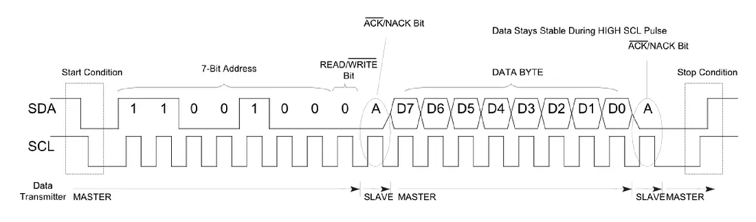
I2C (Inter-Integrated Circuit)
I2C is a synchronous serial communication protocol that allows multiple devices to communicate over a shared bus. It is commonly used for connecting sensors and displays to Arduino.
SPI (Serial Peripheral Interface)
SPI is another synchronous serial communication protocol that is used for high-speed communication between Arduino and devices like displays, memory chips, and other microcontrollers.
UART (Universal Asynchronous Receiver/Transmitter):
UART is the most common form of serial communication used in Arduino. It is asynchronous, which means that data is sent without a shared clock signal. Instead, both the sender and receiver agree on a set of parameters to determine the data rate and timing.
The key parameters in UART communication are:
Baud Rate: This defines the data transmission speed in bits per second (bps). Both the transmitter and receiver must use the same baud rate for successful communication.
Data Bits: The number of data bits in each byte of data. Common values are 8 bits, 7 bits, or 6 bits.
Stop Bits: Stop bits indicate the end of a data byte. Common values are 1 or 2 stop bits.
Parity: Parity bits are optional and can be used for error checking. Common options are no parity, even parity, or odd parity.
https://mypractic.com/lesson-12-serial-port-uart-in-arduino-serial-library-debugging-programs-on-arduino/
Baud Rate
The baud rate determines how quickly data is transmitted over the serial communication channel. It is specified in bits per second (bps). Common baud rates used in Arduino projects include 9600, 19200, 38400, and 115200 bps. Both the sender and receiver must use the same baud rate to communicate successfully.
Choosing the appropriate baud rate depends on factors such as the hardware capabilities of your devices and the required data transfer speed. Higher baud rates allow for faster data transfer but may require more precise timing and can be susceptible to noise and errors over longer distances.
Setting Up Serial Communication
Setting up hardware serial communication is straightforward on Arduino boards with built-in serial ports
Unlike SPI or I2C, which are synchronous, UART is asynchronous, meaning it does not use a clock signal to synchronize the data transmission between devices. However, both devices must agree on the baud rate (speed of transmission).
UART ports allow us to communicate with other devices, such as other microcontroller boards (an Arduino, an ESP8266, another ESP32 board, or others), the computer, sensors, GPS .
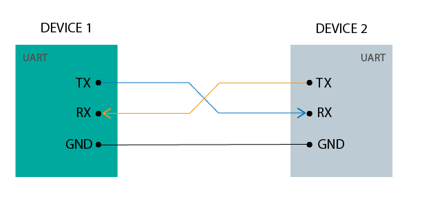
UART Interface
TX (Transmit): Sends data.
RX (Receive): Receives data.
GND GND: Common ground.
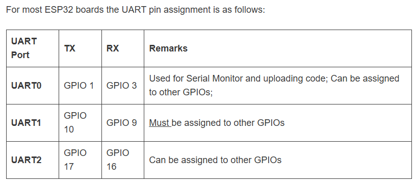
ESP32 UART Peripherals
The ESP32 supports up to three UART interfaces:UART0, UART1 b>, and UART2, depending on the ESP32 board model you’re using.
UART0 is usually reserved for communication with the serial monitor during upload and debugging. However, you can also use it for communication with other devices after uploading the code if the Serial Monitor is not needed.
UART1 and UART2: available to communicate with external devices.
UART0 and the Serial Monitor
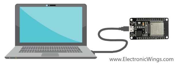
Relation Between UART0 and Serial Monitor. UART0 is the hardware port. Serial Monitor is the software tool on your computer.
When you open Serial Monitor, it connects to the COM port (Windows)
Microcontroller sends data → UART0 TX → USB cable → PC → Serial Monitor shows it.
PC sends data (you type in Serial Monitor) → USB → UART0 RX → Microcontroller receives it.
Setting up serial communication in software involves configuring the serial port with the appropriate settings. Here’s how you can do it in an Arduino sketch.
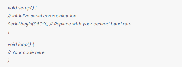
Serial.begin() initializes the serial communication with a specific baud rate. Replace 9600 with the baud rate you intend to use.
demostration in Wokwi
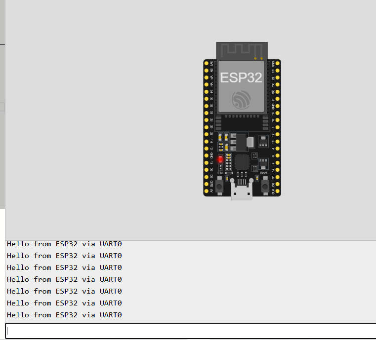
// ESP32 UART0 demo with Serial Monitor
// UART0 is the default "Serial" port connected to USB

void setup() {
  Serial.begin(115200);         // Start UART0
  Serial.println("UART0 Ready!"); // First message to Serial Monitor
}

void loop() {
  // Send data to Serial Monitor
  Serial.println("Hello from ESP32 via UART0");
  delay(1000);

  // If user types something in Serial Monitor, read it
  if (Serial.available() > 0) {
    String input = Serial.readStringUntil('\n');
    Serial.print("You typed: ");
    Serial.println(input);
  }
}


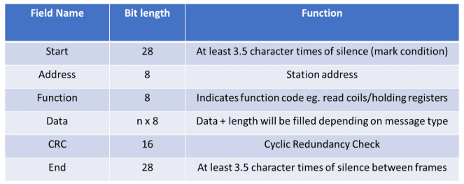
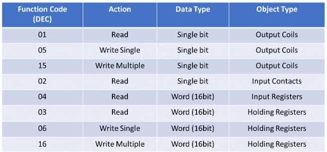
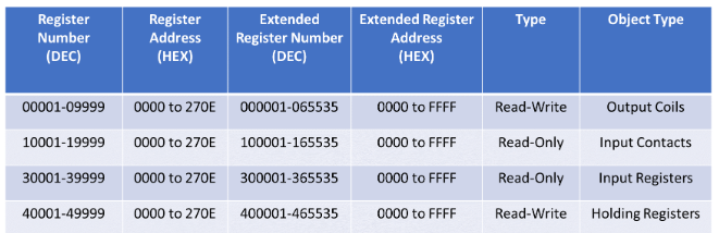
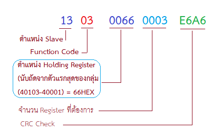
 https://www.sangchaimeter.com/article/310/PLC_MODBUS_RTU
https://www.realpars.com/blog/rs485
https://www.sangchaimeter.com/article/310/PLC_MODBUS_RTU
https://www.realpars.com/blog/rs485